-
Shop Parts
- Shop Accessories
- Shop Overland
-
Shop by Vehicle
![Select Vehicle]() Select Your Vehicle
Select Your Vehicle - Videos & Resources
Sign in to my account
Window Lift Repair Kit
Applies To:
Item: AMR1282RK
Fits: Discovery I | '94 - '99
Range Rover Classic | '95
For Discovery I '95-'99 and Range Rover Classic '95
An internal failure of the Window Lift ECU (Part # AMR128G) will cause no power to the rear window switches. This procedure fixes this problem and this problem alone.
Tools Needed for Kit #AMR1282RK:
- Wire cutter
- Wire stripper
- Panel Fastener Removal Tool (or large flat screwdriver)
Installation Procedure (5 easy steps):
1. To find the Window Lift ECU, drop the glove box to access the area directly behind.
With the glove box door open reach on each side of the box and find the springs. Pull the back part of the spring forward until it aligns with the release slot and slide them out to release the box.
2. Once the box has dropped down you will see the Window Lift ECU mounted vertically to the right. (See Figure #1) Pull the lower connector (8 contact, larger wires) out of its socket and find the White and Pink wire. (See diagram in Figure #2)
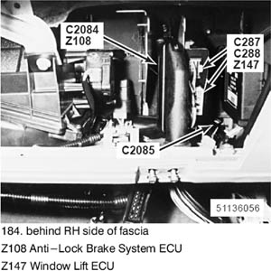
Figure 1. Behind RH Side of Fascia, Z108 Anti-Lock Brake System ECU, Z147 Window Lift ECU.

Figure 2. From back of connector, the White/Pink wire should be in location "H."
Cut this wire about 1 inch from the body of the connector, and strip the harness side (not the connector side) to expose 3/8 inch of bare wire. (See Figure #3) Attach the red wire from Kit #AMR1282RK with the Posi-Lock connector to this wire following the procedure outlined in Appendix "A." Leave the white/pink wire on the connector unattached.
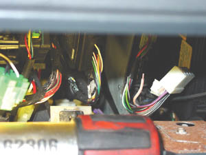
Figure 3.

Appendix "A" Posi-Lock Connector
Plug Connector C288 back into the Window Lift ECU. Feed the wire down behind the glove box so that it will be accessible in the area below the dash. Snap the glove box back into place.
3. Remove the lower footwell panel (3 pop out panel fasteners) and find the wire that you just fed down from above. Find connector #C2073 under the dash to the left side of the wheel well behind the metal bracket (see Figure # 6).

Figure 6. Behind RH Side of Fascia Right of Heater Evaporator Unit. Z210 Condenser Fan Diode 2, C2073 (10-W).
Note: You might have to cut a cable tie to pull the connector out far enough to get access to the wire you need. If you are cutting the cable tie, be careful not to damage any of the wires in the wire bundle. Unplug the connector and pull it down so you have some room to attach the Posi-Tap connector. (See Figures 4 & 5)

Figure 4.

Figure 5.
4. Using the Black Posi-Tap connector from the kit and following the procedure outlined in Appendix "B," tap the White & Green wire. Be sure the point of the Posi-Tap is puncturing the wire as close to the middle of the wire as possible to ensure a good electrical connection. After this wire is tapped, connect the red wire from above to the Posi-Tap using the same procedure (Appendix "B"). Plug connector # C2073 back into it's mate.

Appendix "B" Posi-Tap Connector
5. Test all of the windows, secure the wires with the cable ties provided in the kit and install the footwell panel.
Done!
What Our Customers Are Saying


